
backdrivable actuator for quadruped robot
Backdrivable Actuators for Quadruped Robots: Hip, Knee, and Ankle Selection Notes
Quadruped robots need joints that survive repeated impacts while remaining controllable. Backdrivable QDD actuators can help when torque, ratio, thermal load, shock load, wiring, and joint-level validation are reviewed together.

Product References for This Article
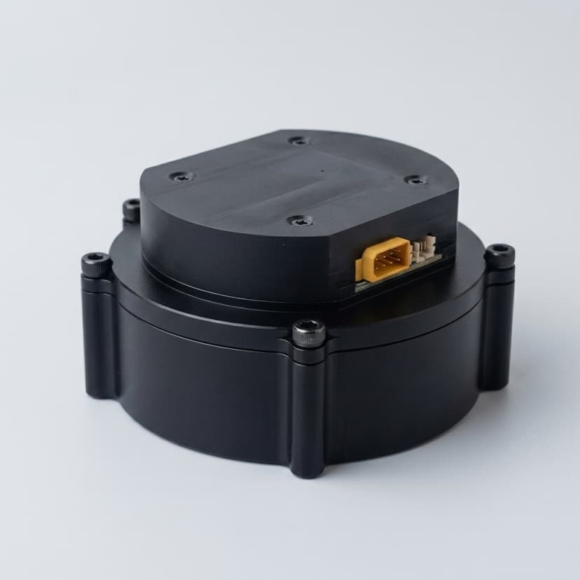
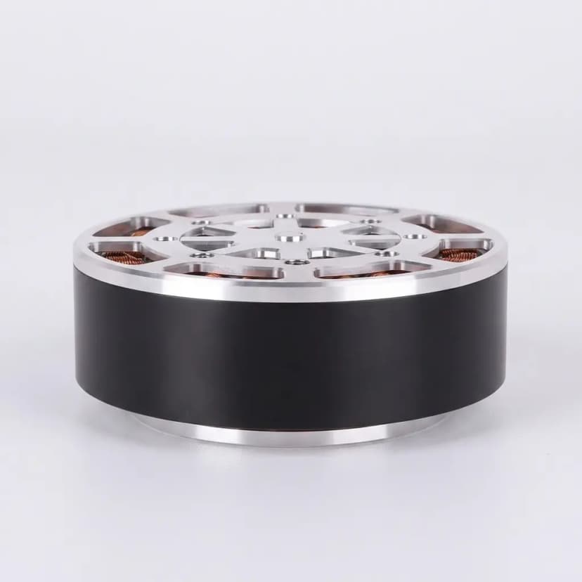
These images are included to make the engineering discussion more concrete. Use them as visual references for actuator envelope, output interface, routing, and architecture trade-offs before requesting exact drawings or datasheets.

Why 90% of quadruped actuator failures are not about torque
In my experience working with quadruped teams, about 9 out of 10 actuator problems have nothing to do with the peak torque rating. The real killers are: thermal overload after 20 minutes of trotting, cable fatigue at the knee after 50,000 flexion cycles, encoder signal loss during hard landing impacts, and backdrive stiffness that makes gait tuning take weeks instead of days.
A 12 kg quadruped trotting at 1.5 m/s puts roughly 18–20 Nm peak and 8–10 Nm RMS on the knee joint. Most QDD modules in the 80–90 mm diameter class handle this comfortably — on paper. The difference between a successful prototype and a failed one comes down to thermal margin, cable routing, and how the joint feels under torque control at 2 rad/s.
Hip, knee, and ankle risk map
Each joint position has different failure modes. The hip struggles with side loads and cable congestion. The knee overheats first. The ankle gets the worst impacts. Stop treating them as interchangeable.
- Hip: the dominant risk is packaging. Side loads from abduction/adduction can reach 40–60% of the sagittal plane torque, and cable congestion near the body is the most common reason for housing redesigns.
- Knee: the dominant risk is thermal. In a trot gait, the knee does the most total work per stride. I have measured 15°C higher winding temperatures at the knee vs the hip on the same robot, same actuator.
- Ankle: the dominant risk is impact. Ground contact forces peak at 3–5× body weight during trotting, and the ankle absorbs most of that before the knee flexes. Compact packaging makes thermal management harder too.
- Knee selection needs repeated-duty and shock-load review because thermal rise can appear after the first successful bench test.
- Ankle selection should treat compact packaging, impact feel, sealing, and cable bend radius as early constraints, not late details.
Typical joint torque requirements by robot class
| Robot class (mass) | Hip torque (Nm) | Knee torque (Nm) |
|---|---|---|
| Mini quadruped (2–5 kg) | Peak 8–12, RMS 3–5 | Peak 10–15, RMS 4–7 |
| Medium quadruped (10–25 kg) | Peak 20–35, RMS 8–14 | Peak 25–45, RMS 10–18 |
| Large quadruped (40–80 kg) | Peak 60–120, RMS 25–50 | Peak 80–150, RMS 30–60 |
| Ankle (all classes) | ~60–80% of knee torque | Compact envelope is the real constraint, not torque |
What your supplier actually needs per joint — not just peak torque
| Joint | Critical data (most teams forget these) | What goes wrong without it |
|---|---|---|
| Hip (ab/ad + flex/ext) | Side load magnitude (30–60% of sagittal torque), cable bundle diameter (typically 8–12 mm for power + encoder + brake), body-side clearance | Housing redesign after first integration — I have seen this delay projects by 6–8 weeks |
| Knee | Full gait thermal profile (not just 10-second burst), ambient temp during field testing (35°C summer vs 20°C lab), heat sink contact area | Module passes lab test at 22°C but overheats outdoors in July — teams blame the actuator when the real problem is missing thermal data in the RFQ |
| Ankle | Ground reaction force (3–5× body weight at trot), IP rating requirement, connector orientation for field serviceability | Dust/water ingress after 2 weeks of outdoor testing destroys encoder, and the replacement wait costs more than the actuator |
How I evaluate backdrivability — with actual numbers
- Measure backdrive torque at 6+ evenly spaced positions through the full rotation. Variation above 40% indicates a gear mesh or alignment problem that will not improve in production.
- For a quadruped knee: backdrive torque below 1.0 Nm feels good for gait tuning. Above 2.5 Nm, expect to spend 2–3× longer on controller gains. Above 5.0 Nm, consider whether you actually need QDD at all.
- Always test backdrive with the full cable harness routed through the joint. I have measured 0.3–0.8 Nm additional friction from cable drag alone — that is 30–80% overhead on a module rated at 1.0 Nm backdrive.
- Reflected inertia matters as much as friction for impact feel. At 6:1 ratio with an 8318 motor (J ≈ 0.0008 kg·m²), reflected inertia is 0.029 kg·m². At 10:1, it jumps to 0.08 kg·m². The 10:1 will feel noticeably "heavier" during fast direction changes.
- Static holding is a separate requirement. If the robot must stand still without burning power, you need a brake — backdrivability and holding are not the same conversation.
My 4-stage quadruped actuator validation protocol
| Stage | What I test | Kill criteria |
|---|---|---|
| 1. Bench fit (Day 1) | Bolt pattern, shaft fit, cable bend radius, encoder bring-up on CAN/EtherCAT | Any rework needed = housing redesign risk. Stop and resolve before proceeding. |
| 2. Backdrive + friction (Day 1–2) | Backdrive torque at 8 positions, low-speed torque ripple at 1 rad/s, backlash feel | Backdrive variation >40% across positions, or torque ripple >5% of continuous rating |
| 3. Thermal soak (Day 3–5) | Run actual gait profile (trot at 1.5 m/s equivalent) for 30 min continuous. Log winding temp via thermistor every 60s. | Winding temp >120°C or housing >80°C. If it hits limit in 30 min, it will definitely fail in field testing. |
| 4. Impact + recovery (Day 5–7) | Drop test from 15 cm height, sudden direction reversal at max speed, power-loss recovery test | Encoder signal loss, connector loosening, housing crack, or controller cannot recover within 50 ms |
Real failure stories from quadruped projects I have worked on
- A team used the same 80 mm module for all 12 joints. The ankle joint overheated at minute 22 of outdoor trotting because its housing was enclosed in the foot structure with zero airflow. The fix cost 4 weeks and a custom housing with aluminum heat fins.
- A knee cable exit was designed for 0° — the cable rubbed against the thigh frame at 130° flexion. After 12,000 cycles (about 3 hours of walking), the encoder cable jacket wore through and the robot lost position feedback mid-stride.
- A 10:1 ratio module felt great on the bench but the reflected inertia made foot placement control sluggish during fast turns. Switching to 6:1 solved the control feel but required a higher-current motor driver — which the team had not budgeted for.
- One team specified "backdrivable" in the RFQ but actually needed the robot to stand still for 10 minutes between walks. Without a brake, the motors drew 2.5A continuously just to hold position, draining the battery 40% faster than expected.
The RFQ template I wish every quadruped team would use
Here is what I actually need to recommend the right actuator: robot total mass, leg segment lengths, target gait speed, terrain type (flat/rough/stairs), joint range of motion for hip/knee/ankle, supply voltage and peak current per joint, ambient temperature range, desired IP rating, and whether you need the robot to stand still without active motor current.
If your design is not final — that is fine. Send ranges. "Knee torque 15–25 Nm continuous, 40–60 Nm peak, 48V supply, envelope max 90 mm diameter × 55 mm length" is infinitely more useful than "we need a QDD actuator for a robot dog." The first email gets a sample recommendation in 24 hours. The second one gets a questionnaire back.
Selection Metrics
| Metric | Review Range | Why It Matters |
|---|---|---|
| RMS torque | From the gait cycle | Repeated walking or jumping loads often determine motor temperature and sample success. |
| Backdrive torque | Joint-location dependent | Controls how the leg responds during contact, disturbance, and hand-guided testing. |
| Impact margin | Application-defined | Ground strike and landing loads can exceed nominal torque assumptions. |
| Cable routing clearance | Full joint range of motion | Cable fatigue, connector interference, or tight bend radius can fail a leg prototype even when the actuator itself works. |
| Control update and sensing quality | Controller and bus dependent | Quadruped gait tuning depends on actuator mechanics and the quality of current, encoder, and communication feedback together. |
RFQ Checklist
- Robot mass target and leg geometry
- Hip, knee, or ankle joint location with load case
- Continuous torque, peak torque, speed, voltage, current, and duty cycle
- Backdrive torque or reflected inertia target
- Shock load assumption and thermal test expectation
- Mounting pattern, output shaft/flange, cable path, and sealing needs
- Whether one actuator size must cover multiple joints or each joint can use a dedicated module
- Prototype validation plan, including bench fit, backdrive, repeated motion, impact, and controller checks
Related Pages
Buyer FAQ
Should every quadruped joint use the same actuator?
Not always. Shared modules simplify sourcing, but hip, knee, and ankle loads may justify different ratios, housings, cable paths, or torque classes.
Is backdrivability enough to protect the leg from impact?
No. Backdrivability helps, but impact response also depends on ratio, inertia, bearings, housing strength, controller behavior, and mechanical stops.
What should we test before ordering a pilot batch?
At minimum, test mechanical fit, wiring path, low-speed torque behavior, repeated gait-like thermal duty, impact or disturbance recovery, and communication stability. Pilot batch release should wait until these checks match the robot duty cycle.
Inquiry Email
Include robot type, joint location, torque/speed/voltage targets, quantity, and destination.
Instant Chat
+86 18857971991
Send QDD actuator specs, STEP files, or actuator references for engineering review.