
EtherCAT vs CAN FD QDD actuators
EtherCAT vs CAN FD in QDD Actuators: Protocol Selection and Sourcing Guide for 2026
Protocol choice changes the actuator PCB, connector count, harness topology, control-loop ceiling, and supplier evidence you need before approving samples. This guide turns EtherCAT vs CAN FD into a practical sourcing screen for QDD actuator buyers.

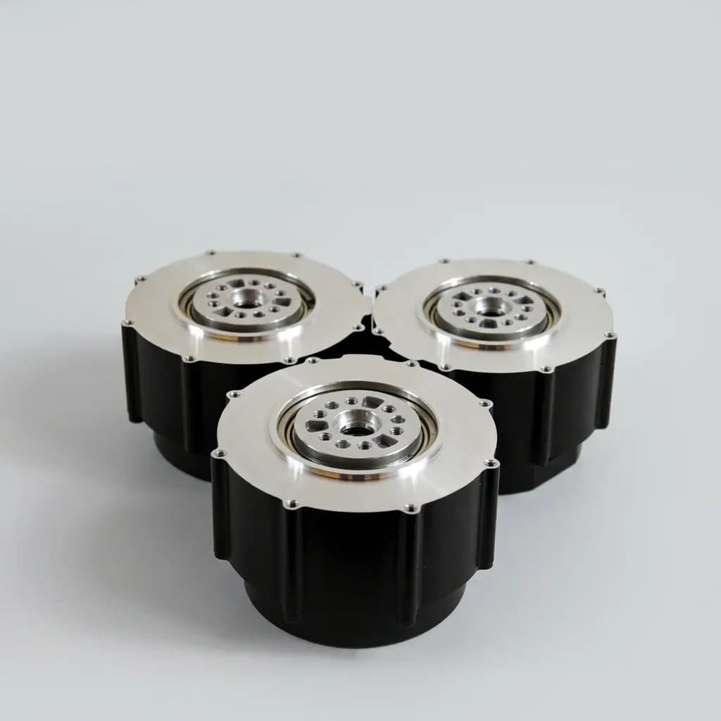
Product References for This Article
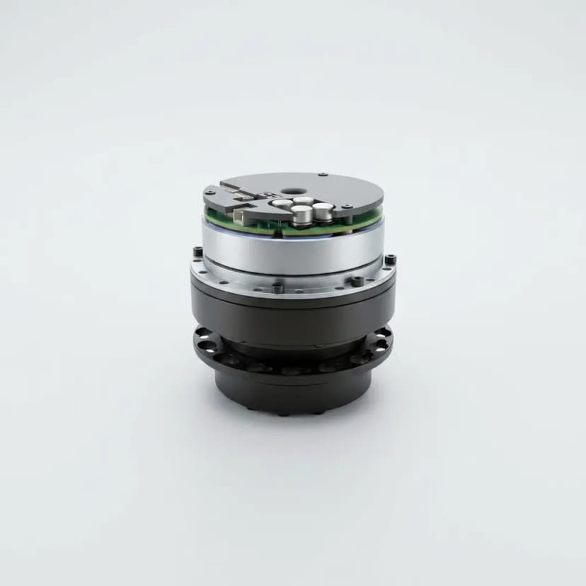
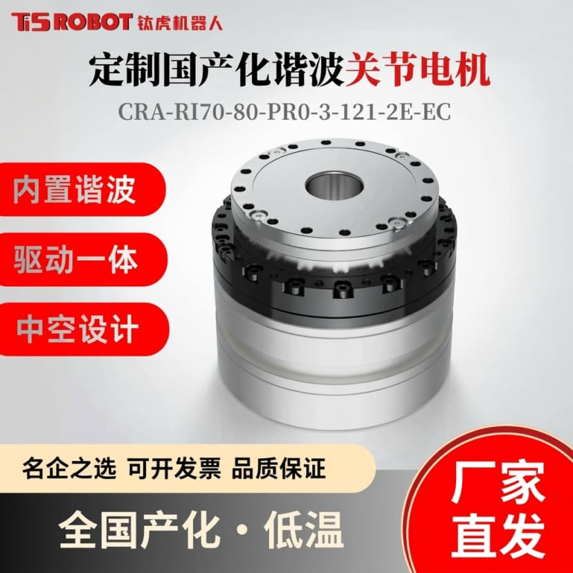
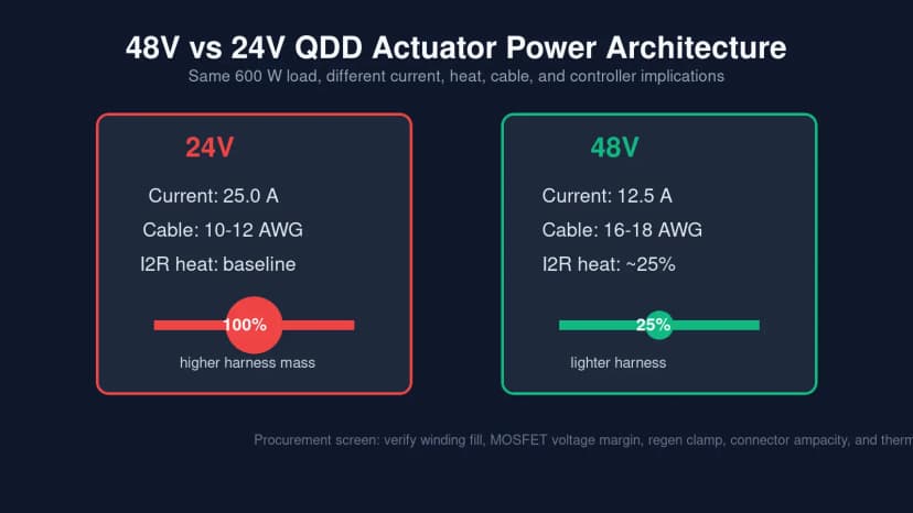
These images are included to make the engineering discussion more concrete. Use them as visual references for actuator envelope, output interface, routing, and architecture trade-offs before requesting exact drawings or datasheets.
Scope, date, and limits
Updated on July 26, 2026, this is a Global sourcing guide for teams comparing integrated QDD actuator modules before architecture lock, RFQ release, sample purchase, or pilot-batch validation.
It does not replace supplier datasheets, signed latency logs, EMC test reports, functional-safety review, or robot-level validation. Use it to decide which communication evidence must be requested before the purchase order.
Why protocol choice changes the whole actuator program
For low-DOF quadrupeds, AMRs, and cost-sensitive prototypes, CAN FD can be the most practical bus because many MCUs already include the controller and the actuator can often keep a single compact connector.
For high-DOF humanoids, bipeds, and synchronized multi-axis platforms, EtherCAT creates more timing headroom through a daisy-chain Ethernet frame and Distributed Clocks, but it adds ASIC, PHY, isolation, connector, shielding, and firmware complexity to every node.
EtherCAT vs CAN FD sourcing matrix
| Review area | CAN FD QDD actuator | EtherCAT QDD actuator |
|---|---|---|
| Practical node count | About 20 to 30 nodes before bus load and arbitration need careful review | 100+ nodes are practical when the slave stack and cabling are engineered correctly |
| Control-loop target | Often suitable for about 1 kHz to 2 kHz on moderate axis counts | Better fit for 4 kHz+ synchronized control on high-axis-count robots |
| BOM adder per actuator | Baseline when the MCU includes CAN FD and only a transceiver is added | Typically adds ESC ASIC, PHY, magnetics, isolation, and dual connectors |
| Connector count | Usually one compact connector for bus and power routing | Usually IN and OUT communication ports, unless a custom backplane is used |
| Synchronization behavior | Microsecond-level timing depends on bus load, scheduling, and firmware design | Distributed Clocks support sub-microsecond synchronization across nodes |
| EMI and shielding | Lower data rate but still needs grounding discipline near motor PWM noise | 100 Mbps twisted-pair routing needs stronger shielding and layout review |
| Supply-chain dependency | Depends mostly on MCU and CAN transceiver availability | Adds dependency on EtherCAT slave controller and approved firmware stack |
| Best-fit sourcing stage | Early prototypes, compact robots, AMRs, and cost-sensitive platforms | Locked high-DOF robots, humanoids, bipeds, and demanding WBC platforms |
Supplier evidence checklist before sample approval
- Master compatibility: SOEM, TwinCAT, SocketCAN, ROS2 bridge, or the exact controller stack the robot will run.
- Bus-load calculation using target update rate, payload size, number of joints, encoder fields, current feedback, and diagnostic messages.
- Latency and jitter capture from the same actuator firmware, not from an unloaded demo board.
- Connector family, pinout, cable bend radius, shielding, and grounding note for the final robot harness.
- EMI evidence near PWM switching noise, encoder feedback, and any high-current phase-lead routing.
- Firmware update path over the chosen bus, including rollback behavior for 20+ or 30+ actuator fleets.
- Fault handling: node timeout, bus-off recovery, EtherCAT chain break behavior, and ring-redundancy option if required.
- Production documents: ESI or CAN database file, object dictionary, register map, watchdog behavior, and acceptance test log.
When CAN FD is the better procurement answer
Choose CAN FD when cost, compact packaging, field replacement, and supplier flexibility matter more than maximum synchronization headroom. It is often the better first sample path for smaller AMRs, low-DOF quadrupeds, education platforms, and early mechanical prototypes.
The caveat is scale. Once bus utilization is high, every extra joint, diagnostic frame, and current feedback field increases latency risk. Procurement should ask for a real bus-load worksheet before assuming CAN FD will scale to the final robot.
When EtherCAT is worth the BOM premium
Choose EtherCAT when the robot needs high-axis-count synchronization, deterministic timing, and a mature real-time control stack. Humanoids, bipeds, and ultra-precise multi-axis platforms can justify the extra communication hardware because control-loop timing becomes a system-level limit.
The caveat is supplier maturity. A low-cost EtherCAT actuator without proven EMC layout, stable ESI files, watchdog behavior, and firmware update discipline can create more launch risk than a well-engineered CAN FD design.
Decision rule for 2026 QDD sourcing
Use CAN FD as the default review path when the robot has modest axis count, target updates near 1 kHz, tight actuator packaging, and strong unit-cost pressure.
Use EtherCAT when the platform is high-DOF, needs 4 kHz+ synchronized control, requires tighter distributed timing, or must align with an existing EtherCAT real-time master. The final decision should be based on measured bus load, jitter, EMC behavior, and supplier evidence, not protocol branding.
Selection Metrics
| Metric | Review Range | Why It Matters |
|---|---|---|
| Target control-loop rate | 1 kHz to 4 kHz+ depending on robot dynamics | The update period defines how much time the bus has to command and read every joint. |
| Axis count on one network | 12 to 30+ QDD actuator nodes | Every added node increases payload, timing, wiring, and fault-containment requirements. |
| Bus-load margin | Keep enough margin for diagnostics, retries, and future firmware fields | A bus that only works in a nominal demo can fail once diagnostics and safety traffic are added. |
| Jitter under PWM noise | Supplier-specific; request oscilloscope or bus-analyzer logs | Motor switching noise can corrupt feedback timing even when bench bandwidth looks acceptable. |
| Connector and PCB volume | CAN FD often 1 connector; EtherCAT often 2 communication ports | Connector count can block compact joint envelopes and increase harness service time. |
| Communication BOM premium | EtherCAT adds ASIC, PHY, isolation, magnetics, and cabling cost | For 20 to 30 joints, protocol hardware becomes a visible part of the actuator program budget. |
RFQ Checklist
- Robot type, axis count, target loop rate, update payload per joint, and required diagnostic fields
- Chosen master stack, OS, real-time kernel assumptions, and ROS2 integration boundary
- CAN FD bus-load worksheet or EtherCAT cycle-time calculation using the final joint count
- Communication connector type, pinout, cable bend radius, branch length, shielding, and grounding plan
- Latency, jitter, synchronization, and dropped-frame logs captured under motor PWM noise
- Firmware update, object dictionary or register map, watchdog, timeout, and bus recovery behavior
- Safety requirement: FSoE, STO boundary, emergency stop behavior, or robot-level safety controller interface
- Supplier documents: ESI file, CAN database, EMC notes, production test report, warranty boundary, and sample lead time
Related Pages
Buyer FAQ
Can a CAN FD to EtherCAT gateway solve protocol mismatch?
It can bridge systems, but it usually adds latency, configuration complexity, and another failure point. Use a gateway only when the timing budget has been measured and accepted.
Are CAN FD QDD actuators always cheaper?
Usually, but not automatically. CAN FD removes EtherCAT slave hardware, yet supplier firmware maturity, cable design, diagnostics, and validation effort still affect total cost.
Does EtherCAT make every QDD actuator physically larger?
Not always, but dual ports, magnetics, isolation, and ESC placement can force a larger backplate or a more complex connector stack in compact actuators.
What should we ask for beyond a protocol name on the datasheet?
Ask for the ESI file or CAN database, object dictionary or register map, bus-load calculation, latency/jitter logs, EMC notes, watchdog behavior, and firmware update process.
When does FSoE make EtherCAT mandatory?
If the robot safety architecture requires Fail Safe over EtherCAT, supplier protocol choice is no longer a preference. Confirm this during safety review before buying actuator samples.
Sources & References
- EtherCAT Technology Group
Official EtherCAT technology reference for processing-on-the-fly communication and Distributed Clocks context.
- Bosch CAN FD Protocol
Protocol-owner reference for CAN FD communication context, payload, and higher data-rate assumptions.
- Highly Dynamic Quadruped Locomotion via Whole-Body Impulse Control and Model Predictive Control
Research context for high-dynamic legged robot control where synchronized actuator updates affect platform performance.
- Design and Characterization of 3D Printed, Open-Source Actuators for Legged Locomotion
Open QDD actuator reference for legged locomotion actuator design, characterization, and validation context.
Inquiry Email
Include robot type, joint location, torque/speed/voltage targets, quantity, and destination.
Instant Chat
+86 18857971991
Send QDD actuator specs, STEP files, or actuator references for engineering review.