
48V vs 24V QDD actuators
48V vs 24V QDD Actuators: Power Architecture and Sourcing Guide for 2026
Choosing 24V or 48V changes current, harness mass, stator winding, motor-driver voltage margin, regenerative braking protection, and battery architecture. This guide turns the physics into a sourcing screen for QDD actuator RFQs.

Product References for This Article
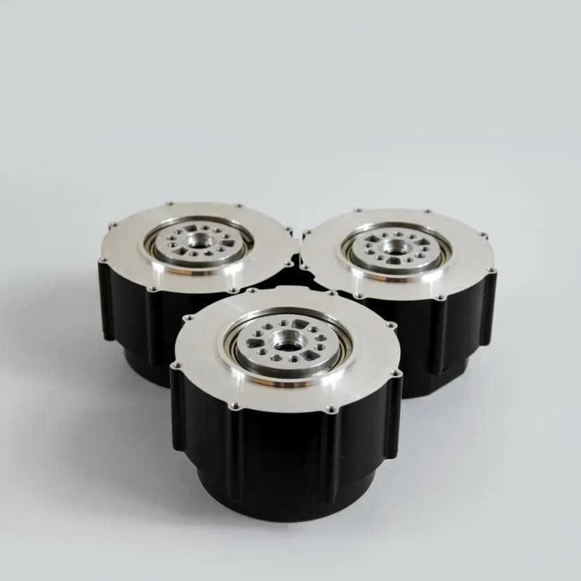
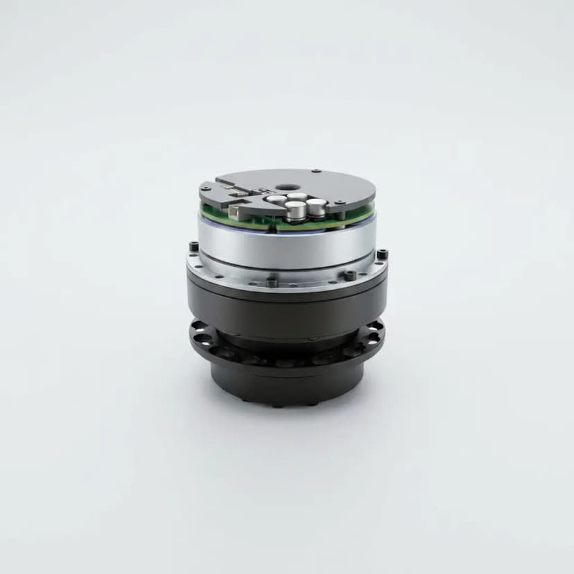
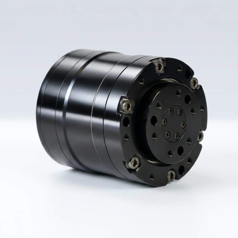
These images are included to make the engineering discussion more concrete. Use them as visual references for actuator envelope, output interface, routing, and architecture trade-offs before requesting exact drawings or datasheets.
Scope, date, and limits
Updated on July 24, 2026, this is a Global sourcing screen for procurement teams and application engineers comparing integrated QDD actuator modules before architecture lock, sample purchase, RFQ release, or pilot-batch validation.
It does not replace supplier datasheets, signed thermal logs, EMC validation, regenerative braking tests, battery safety review, or compliance sign-off on the final robot. Use it to define the evidence your supplier must provide before the purchase order.
Why the voltage decision changes the whole joint
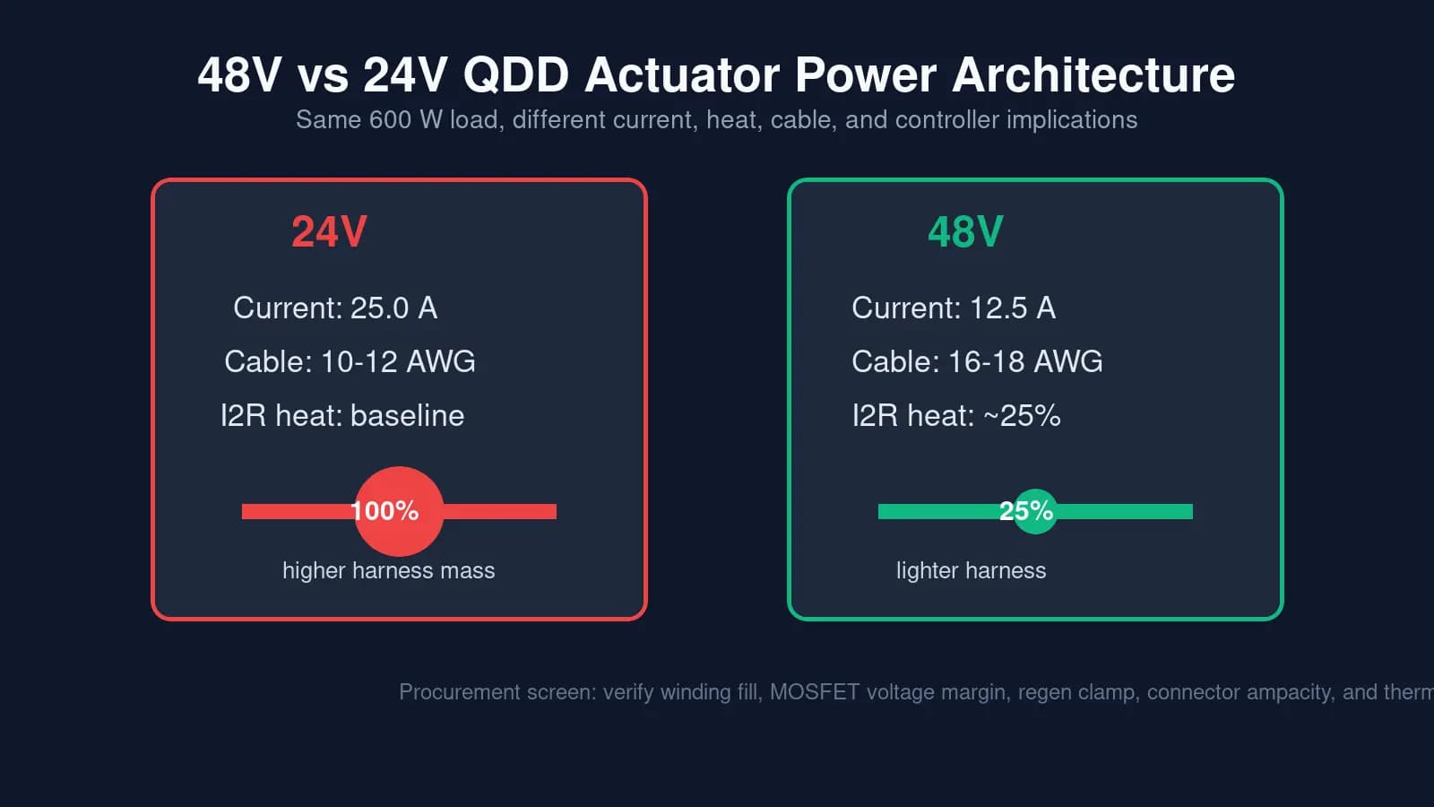
For the same electrical power, doubling bus voltage halves current. That matters because cable and winding heat follows I2R loss, so lower current can sharply reduce heat in phase leads, connectors, slip rings, and compact joint electronics.
The benefit is not free. A 48V QDD actuator needs a different winding, higher-voltage MOSFET margin, regenerative braking protection, battery and BMS review, and more disciplined EMC validation than a simpler 24V robot bus.
24V vs 48V QDD sourcing matrix
| Review area | 24V QDD architecture | 48V QDD architecture |
|---|---|---|
| Peak current at equal power | Higher current, often 30A to 40A in dynamic joints | Roughly half the current for the same electrical power |
| Cable gauge and routing | Thicker 10 to 12 AWG phase wiring may raise limb mass and bend fatigue | Lighter 16 to 18 AWG wiring can simplify moving-limb harness design |
| Cable heat | Baseline I2R heat loss in cables and connectors | About 25% of the resistive heat if resistance is unchanged |
| Controller voltage margin | Lower-cost MOSFET choices and wider off-the-shelf controller availability | Needs 80V or 100V device margin to tolerate bus spikes |
| Stator winding | Thicker wire and fewer turns are easier to wind and inspect | Thinner wire and more turns need stronger fill-factor process control |
| Regenerative braking risk | Lower bus-spike stress in many small robot platforms | Higher risk when a full battery or BMS disconnect blocks energy recovery |
| Best-fit robot type | Desktop arms, education, low-torque prototypes, stationary fixtures | Legged robots, humanoids, exoskeletons, and heavy-payload AMRs |
| Procurement risk | Lower electronics complexity but higher harness mass at high power | Better power density but stricter supplier evidence is required |
Supplier evidence checklist before sample approval
- Battery architecture and voltage window, including 7S, 13S, or 14S chemistry assumptions.
- Winding design evidence: Kv target, fill factor, automated winding process, and stator inspection method.
- Controller MOSFET voltage rating, current rating, thermal path, PWM frequency, and protection behavior.
- Regenerative braking plan: active clamp, dump resistor, BMS interaction, and bus overvoltage logs.
- Connector and harness ampacity with derating for enclosed joints and repeated cable flexing.
- Continuous torque curve at the selected voltage, not only a shared peak-torque number.
- EMC and encoder shielding plan, especially for high dV/dt 48V switching edges.
Regenerative braking is the 48V failure mode to screen
QDD actuators are backdrivable, so hard deceleration, landing impacts, or abrupt AMR braking can push kinetic energy back into the DC bus. A 48V system running from a fully charged 13S or 14S pack has less headroom before a regenerative spike stresses the controller.
Before approving a 48V actuator, ask whether the supplier has tested overvoltage behavior with a full battery, a BMS disconnect event, and the actual controller firmware. A cheap 48V module without a clamp or dump path can fail long before the motor reaches its torque limit.
Architecture decision rule for 2026 sourcing
Use 48V as the default review path when harness mass, continuous heat, dynamic peak power, and robot agility are serious constraints. Use 24V when the platform is small, stationary, educational, cost-sensitive, or already standardized around mature 24V industrial components.
The safest sourcing process is to decide battery architecture first, then request voltage-specific torque, thermal, harness, controller, and regenerative braking evidence from the actuator supplier before sample approval.
Selection Metrics
| Metric | Review Range | Why It Matters |
|---|---|---|
| Peak current at target power | 24V: about 2x 48V current for equal power | Current drives cable size, connector selection, controller heating, and bus distribution cost. |
| I2R heat reduction | 48V can reduce resistive heat to about 25% when current halves | Thermal margin is often the limiting factor in compact QDD joints and moving robot limbs. |
| Cable gauge | 24V often 10-12 AWG; 48V often 16-18 AWG for similar power | Harness mass, bend radius, and fatigue life directly affect legged robots and exoskeletons. |
| Controller voltage margin | 48V systems commonly need 80V or 100V-rated power devices | Regenerative spikes can exceed nominal voltage and destroy underspecified controller boards. |
| Winding fill factor | Supplier-process dependent | Poorly executed 48V winding can erase expected efficiency gains and increase cogging. |
| Regenerative braking protection | Clamp circuit, dump resistor, firmware limit, or battery absorption path | Backdrivable QDD joints can return energy to the bus during impacts, landings, and braking. |
RFQ Checklist
- Robot type, joint location, payload, target speed, peak torque, RMS torque, and repeated duty cycle
- Battery chemistry, nominal voltage, maximum charged voltage, BMS behavior, and current limit
- Desired winding Kv, speed ceiling, torque constant, and whether 24V and 48V variants share geometry
- Phase wire gauge, cable flex target, connector family, slip-ring use, and derating assumptions
- Controller MOSFET voltage rating, current rating, heat sink path, and firmware protection thresholds
- Regenerative braking evidence: bus-spike logs, clamp circuit, dump resistor sizing, and BMS-disconnect test
- Continuous torque and thermal-soak curve measured at the selected voltage and mounting condition
- Required documents: CAD, pinout, wiring note, torque-speed curve, EMC notes, warranty boundary, and sample lead time
Related Pages
Buyer FAQ
Can we swap a legacy 24V robot to 48V QDD actuators for more torque?
No. Torque is primarily tied to current and motor design, not voltage alone. A 48V migration usually requires battery, BMS, wiring, controller, protection, and validation changes.
Why not move from 48V to 96V or 400V?
Higher voltage can reduce current further, but it also raises insulation, connector, service, safety, and certification requirements. Many mobile robots stay near 48V to balance power density and low-voltage handling complexity.
Can a 24V QDD actuator run from 48V if software limits PWM?
It may work on a bench, but it is not a strong production strategy. It reduces control margin, can increase ripple and heat, and depends on software never commanding an unsafe duty cycle.
Does voltage change QDD backdrivability?
Voltage does not directly define backdrivability. Gear ratio, bearing friction, cogging torque, encoder behavior, and cable drag matter more, although poor winding execution can affect joint feel.
Are 48V QDD actuators more difficult for EMC?
They can be. Higher bus voltage and fast switching edges increase dV/dt, so encoder shielding, cable routing, grounding, and protocol robustness need stricter review.
Sources & References
- Design and Characterization of 3D Printed, Open-Source Actuators for Legged Locomotion
Open research reference for quasi-direct-drive actuator design, characterization, thermal behavior, and low-cost legged locomotion use cases.
- Texas Instruments Motor Drivers
Motor-driver product-category reference for controller architecture, protection, voltage class, and power-stage selection context.
- Highly Dynamic Quadruped Locomotion via Whole-Body Impulse Control and Model Predictive Control
Research context for dynamic quadruped operation where actuator power density, current delivery, and torque-control behavior affect platform performance.
Inquiry Email
Include robot type, joint location, torque/speed/voltage targets, quantity, and destination.
Instant Chat
+86 18857971991
Send QDD actuator specs, STEP files, or actuator references for engineering review.