
dual encoders in QDD actuators
Dual Encoders in QDD Actuators: Joint Calibration, Backlash Compensation, and Sourcing Guide for 2026
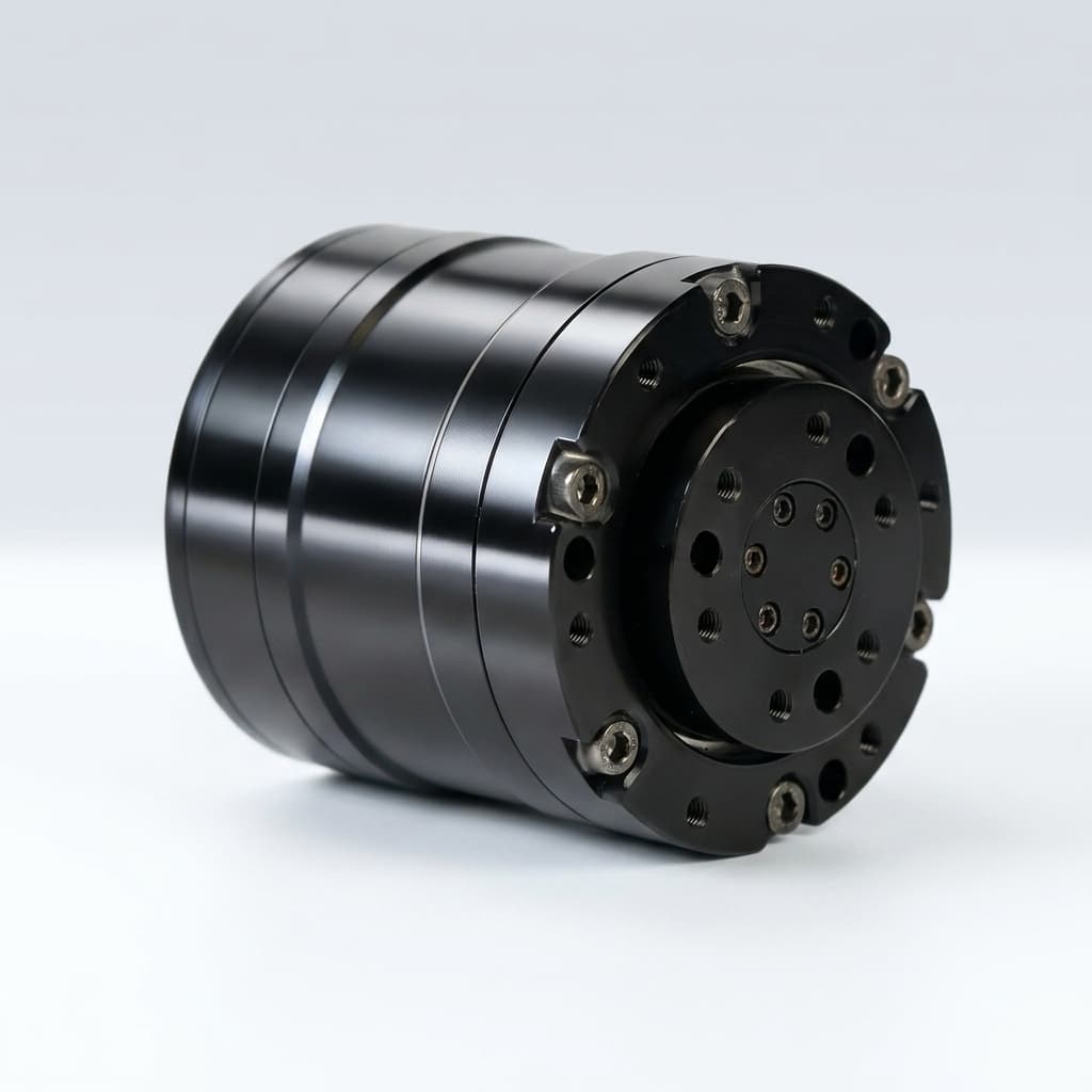
Dual encoders in QDD actuators measure both motor rotation and joint output position. Choose this architecture when gearbox clearance, compliance, or startup position uncertainty could exceed your joint error budget. The motor encoder supports commutation and velocity control; the output encoder closes the position loop after the reducer. Feedback can reduce positioning error caused by backlash, but it cannot remove mechanical clearance or guarantee torque accuracy.

Scope, review date, and sourcing decision
Updated on October 27, 2026, this Global, English-language guide supports engineering and procurement decisions before architecture lock, sample purchase, RFQ release, or pilot-batch production. It compares feedback arrangements, calibration evidence, and supplier acceptance tests. It does not rank suppliers or establish current market prices, safety certification, or measured actuator performance. Numerical examples are calculations or proposed test inputs, not factory results.
For a sample review, prepare your joint range, output-angle tolerance, load cycle, bus timing budget, quantity, and destination, then use the inquiry at the end of this guide.
1. When Does a Single Motor Encoder Fall Short?
A QDD joint combines a motor with a low-ratio reducer. For a reduction ratio N, motor inertia reflected to the output is J_motor × N². A lower ratio reduces that contribution compared with a higher ratio using the same motor; actual backdrivability also depends on friction, preload, bearings, and the complete transmission.
1.1 Backlash and Output Position Error
A controller using only the motor encoder estimates joint angle as θ_motor / N, after applying direction and zero offsets. Gear clearance and elastic deformation can make that estimate differ from the output angle. Output feedback observes the downstream motion, helping the controller correct position within its torque, bandwidth, and stability limits.
Backlash compensation is not backlash elimination. Clearance still exists when load changes direction. Ask for a loaded reversal test rather than accepting an encoder bit count as proof of mechanical precision.
1.2 Torsional Compliance
Define the deflection consistently as δ = θ_motor / N − θ_output, with both angles unwrapped, synchronized, and referred to the same calibrated zero. In a simplified elastic model, transmitted torque is approximately τ = K × δ, where K is torsional stiffness in Nm/rad. This model is unreliable in the clearance zone and can vary with temperature, load direction, friction, and wear.
1.3 Absolute Position and Startup
A single-turn motor encoder repeats once per motor revolution, so it may leave several possible output angles after power loss. A motor multi-turn encoder, a constrained joint range, or an independent reference can resolve that ambiguity; a single-encoder design does not always require hard-stop homing.
An absolute output encoder measures joint angle within one output revolution. Avoiding a homing move also requires a valid mechanical-zero offset, completed startup diagnostics, and a suitable turn-count strategy. Continuous-rotation joints need verified multi-turn behavior, including movement while unpowered.
2. Dual Encoder Topology: Dividing the Responsibilities
Synapticon's dual-loop control documentation assigns motor-side feedback to commutation and velocity, and output-side feedback to position. Its configuration also requires the correct gear ratio. This is a useful architecture reference, not a performance guarantee for another manufacturer's drive.
2.1 Primary Motor Encoder: Commutation and Velocity
The primary encoder measures rotor angle for Field-Oriented Control (FOC), with electrical angle determined using the motor pole-pair count and commutation offset. Specify feedback update rate, noise, delay, and alignment requirements with the drive supplier. A current-loop execution rate does not by itself establish torque-control bandwidth.
2.2 Secondary Output Encoder: Joint Position
The output encoder measures the flange after the reducer. Ring or off-axis designs can preserve a hollow bore, but not every QDD joint uses this arrangement. Request the exact encoder model, mounting location, single-turn or multi-turn capability, calibrated accuracy, and feedback timing. More bits provide finer quantization, not automatically better accuracy.
2.3 Can Differential Angle Estimate Torque?
Differential feedback can support a torque observer if transmission deflection is large enough to measure and the stiffness model is calibrated. Current-based estimates additionally depend on the torque constant, reduction ratio, losses, and dynamics. Neither method establishes a universal percentage accuracy.
For illustration, assume K = 1,000 Nm/rad and a measured deflection of 0.01°. The elastic estimate is 1,000 × 0.01 × π / 180 ≈ 0.175 Nm. If the combined angular error is also 0.01°, its torque-equivalent uncertainty is about 0.175 Nm before other model errors. This calculation explains why a stiff joint may still need a torque sensor. Validate the observer against a calibrated reference over both load directions, temperature, and speed.
3. Sensor Technologies: Magnetic vs Optical vs Inductive
The RLS rotary magnetic encoder catalog is a manufacturer reference for available magnetic feedback arrangements. Select an exact part and its datasheet before assigning accuracy, packaging, or environmental limits.
3.1 Magnetic Ring Encoders
Magnetic designs can suit compact, contaminated environments, but do not make the complete actuator waterproof. Air gap, eccentricity, ring magnetization, temperature, and stray magnetic fields can affect error. Request motor-current-on accuracy measurements and the supplier's interference mitigation plan; shielding is one possible measure, alongside placement and sensor selection.
An aluminum enclosure can attenuate some electromagnetic interference, but it does not reliably shield static or low-frequency magnetic fields. Verify any magnetic shielding in the actual assembled geometry.
3.2 Optical Encoders
Optical designs can provide fine resolution and high accuracy, depending on the scale and readhead. Contamination and condensation can affect open optical paths; shock tolerance depends on the actual construction and mounting. Do not classify every optical encoder as fragile or every magnetic encoder as shock-proof. Use our IP67 waterproof QDD actuator guide to define housing-level evidence, including connectors and seals.
3.3 Inductive Encoders
Inductive designs are another option when contamination or magnetic interference is a concern. Target geometry, air gap, runout, conductive surroundings, and electronics still need validation. No sensing principle alone establishes IP67 compliance, functional safety, or immunity to every interference source.
4.1 Internal Readhead Interfaces: BiSS-C, SSI, and SPI
The BiSS Association describes an open standard with CRC protection and a register communication channel. For a quoted BiSS-C encoder, confirm its implemented frame, clock limit, electrical interface, and error handling; link timing does not establish closed-loop bandwidth.
Basic SSI implementations may lack a CRC, while device-specific extensions vary. SPI is commonly used for short internal connections; allowable distance depends on signal integrity, transceivers, and the device specification. Request actual interface documents rather than treating a protocol label as an interoperability guarantee.
4.2 EtherCAT and CAN-FD Telemetry
Do not assume a fieldbus exposes both raw encoders or that a position object always refers to the output flange. Request an object dictionary or CAN message definition showing motor and output positions, units, signs, scaling, timestamps, validity flags, and torque-estimate meaning. Encoder-angle difference is not itself a torque value.
A proposed 4 kHz update period leaves 1 / 4,000 = 250 μs per cycle. Measurement conversion, filtering, transfer, scheduling, and sample age all belong in the budget. Verify end-to-end delay, jitter, synchronization, and stale-feedback behavior at the intended axis count with PWM active. A nominal bus period alone cannot establish fresh feedback on every cycle.
5. Factory Calibration: What Evidence to Request
Two encoders with the same advertised bit depth may differ in calibrated error, repeatability, latency, and production testing. Request separate quote lines for sensing hardware, calibration, validation, and recurring production inspection; this guide provides no verified supplier-price survey.
For an assembled joint, request a traceable output-angle reference, measurements in both directions over the working range, the reference uncertainty, test temperature, load, supply conditions, and serial-number linkage. A Look-Up Table (LUT) can correct repeatable error, but it does not remove all temperature drift, hysteresis, or wear. A correction method is acceptable only if the resulting joint meets the agreed error limit.
Reproducible Example: Resolution vs Application Accuracy
Assume a 15-bit motor encoder and an 8:1 reducer. One motor count referred to the output is 360° / (2¹⁵ × 8) = 0.001373°. An 18-bit output encoder has the same nominal count step: 360° / 2¹⁸ = 0.001373°. In counts, the comparison is C_output = N × C_motor; in bits it is b_output = b_motor + log₂(N). This is a quantization comparison, not a mandatory resolution ratio or an accuracy certificate.
For a single joint with a 0.5 m lever arm and a proposed 0.5 mm tip-error allowance, the small-angle budget is 0.0005 / 0.5 = 0.001 rad ≈ 0.0573°. A hypothetical residual joint-angle error of 0.03° would contribute about 0.5 × 0.03 × π / 180 = 0.000262 m, or 0.262 mm, before link flex, other joints, and load effects. These are assumed inputs and calculated results, not measured calibration outcomes.
Use that budget to agree acceptance limits, then ask for pre-correction and residual error curves. Record calibration version, stored zero, firmware compatibility, and the process after encoder or bearing replacement.
6. Sourcing Comparison: Six Feedback Configurations
| Architecture | Output observability | Main sourcing and acceptance question |
|---|---|---|
| A. Single magnetic motor encoder | Motor motion only; output error is inferred | Can the calibrated estimate meet the loaded joint error budget? Check startup ambiguity. |
| B. Single optical motor encoder | Finer motor feedback may still miss gearbox error | Does increased motor resolution improve the limiting error? Confirm mounted accuracy and environmental limits. |
| C. Motor encoder + absolute magnetic output encoder | Direct output position within specified range and accuracy | Request current-on error, air-gap tolerances, calibration records, and startup validation. |
| D. Motor encoder + absolute optical output encoder | Direct output position within specified range and accuracy | Request contamination, condensation, shock, and mounting evidence for the selected assembly. |
| E. Dual encoders + calibrated joint torque sensor | Position plus an independent torque measurement | Compare torque range, uncertainty, overload, drift, bandwidth, and integration cost with observer requirements. |
| F. Dual encoders with multi-turn output feedback | Output angle plus retained turn count within its specified range | Verify unpowered motion tracking, retention method, maintenance, turn limits, and restart fault behavior. |
Interpreting the comparison
These six configurations are a decision framework, not a market-price ranking. IP rating belongs to the tested assembly in every row. Request configuration-specific quotes with the same volume, currency, delivery terms, calibration scope, and warranty.
If loaded output accuracy is already adequate with a single encoder, dual feedback may add cost and integration effort without solving the main limitation. If it is inadequate, compare output feedback with mechanical improvements rather than expecting control software to remove clearance.
9. Preparing a Configuration-Specific Inquiry
Specify dual feedback when direct output measurement addresses a documented error or startup requirement. Approve the configuration using residual accuracy, loaded reversal behavior, timing, thermal tests, and power-loss results—not bit depth alone.
For sample and sourcing review, share your robot type, joint range, load and speed cycle, error budget, supply voltage, bus, quantity, destination, and schedule. Request the exact encoder part numbers, STEP model, calibration evidence, timing logs, and an itemized quote. Confirm availability and qualification scope for the proposed configuration before purchase.
Evidence and source limits
Sources checked on October 27, 2026. Manufacturer documentation describes its own implementations; it does not certify another supplier's actuator. The calculations and RFQ acceptance framework are editorial engineering analysis, not first-party hardware test data.
Selection Metrics
| Metric | Review Range | Why It Matters |
|---|---|---|
| Output angle acceptance | Application-defined; 0.0573° is the worked single-joint budget | Separate encoder residual error from load, link flex, and other joint errors. |
| Count step in the worked example | 0.001373° for 15-bit motor feedback at 8:1 or 18-bit output feedback | Quantization equivalence does not prove calibrated accuracy. |
| Sample age and skew | Application-defined; 250 μs is an illustrative 4 kHz period | Include conversion, filtering, transport, and scheduling delays. |
| Torque observer uncertainty | Validate against a calibrated reference over the intended envelope | No universal percentage accuracy follows from using two encoders. |
| Restart position validity | Verify single-turn range, turn retention, stored zero, and startup diagnostics | An absolute sensor alone does not establish safe startup behavior. |
| Environmental qualification | Selected encoder limits and assembly-level evidence | Sensor principle alone does not establish IP rating or shock tolerance. |
RFQ Checklist
- 1. Define the joint error budget: Specify range, load, temperature, repeatability, and permitted output error. Separate resolution from calibrated accuracy; use the count comparison above only for quantization screening.
- 2. Verify interference behavior: Request assembled-joint error logs with representative motor current, wiring, and external fields. Review layout and shielding where needed; an aluminum cover alone is not magnetic shielding evidence.
- 3. Audit calibration traceability: Request serial-linked residual curves, reference uncertainty, both rotation directions, correction version, and a mechanical-zero procedure. Accept the correction method based on demonstrated residual error.
- 4. Set thermal acceptance conditions: Define operating temperatures and load cycles from the application. Ask for cold and hot error curves plus sensor and magnet temperature limits; avoid an unexplained universal drift threshold.
- 5. Measure timing and faults: Budget total sample age and skew, then request end-to-end logs at the intended bus load. Confirm CRC/error flags, stale-data timeout, and the configured response to encoder loss.
- 6. Check mechanical integration: Request mounting stack-up, allowable air gap and runout from the selected encoder datasheet, bearing-load limits, and an assembly-level ingress report where required.
- 7. Test power loss and service: Move the joint through representative positions while unpowered, restart with motion inhibited, and compare reported angle to a reference. Confirm turn retention, zero storage, and recalibration after repair.
Related Pages
Buyer FAQ
Do dual encoders eliminate gearbox backlash?
No. They observe output motion after the reducer and can support compensation within control limits. Mechanical clearance remains; verify loaded reversal error and closed-loop stability on the assembled joint.
Are magnetic encoders always better than optical encoders for QDD joints?
No. Compare the exact parts for calibrated accuracy, contamination, shock, temperature, stray fields, mounting, and latency. The sensor principle alone does not establish actuator ingress protection or durability.
Do dual encoders replace a joint torque sensor?
Only if a validated observer meets the application's uncertainty, bandwidth, and fault-detection requirements. A stiff drivetrain, backlash, friction, or angular measurement error can limit deflection estimates. Position feedback alone provides no safety-rated torque measurement.
Does an aluminum housing protect a magnetic encoder from all stray fields?
No. Static and low-frequency magnetic fields require appropriate sensor selection, placement, and, where needed, magnetic shielding. Test the assembled actuator under representative current and external-field conditions.
Does an absolute output encoder always remove homing?
It may avoid a reference move within its absolute range after zero calibration and startup checks. Multi-turn travel requires a verified turn-count mechanism; test externally moved joints after power loss and after service.
Can a single-encoder actuator be upgraded later?
Only if the supplier designed suitable mechanical mounting, electronics, firmware inputs, and a calibration process. Request revision-controlled CAD and a supported upgrade procedure before ordering. There is no universal axial-thickness or retrofit-cost allowance.
Sources & References
- Synapticon: Dual Loop Cascaded Position Control
Direct reference for assigning input feedback to commutation/velocity and output feedback to position, with gear-ratio configuration.
- RLS: Rotary magnetic encoders
Manufacturer catalog for magnetic encoder options; use the selected part's datasheet for actual limits.
- BiSS Association: The High Performance BiSS Interface
Protocol-owner overview supporting CRC protection and register-channel discussion, not actuator bandwidth claims.
- Kim et al.: Highly Dynamic Quadruped Locomotion via Whole-Body Impulse Control and Model Predictive Control
Primary research context for dynamic legged control; not evidence of dual-encoder pricing, calibration accuracy, or torque-observer performance.
Inquiry Email
Include robot type, joint location, torque/speed/voltage targets, quantity, and destination.
Instant Chat
WhatsApp Engineering Support
Send QDD actuator specs, STEP files, or actuator references for engineering review.